Sunday, June 12, 2022

Toyota Camry Engine Control Unit Wiring Diagram


toyota camry wiring diagrams 1998 to 2016 youtube.

this video demonstrates the toyota camry definite wiring diagrams and details of the wiring harness diagrams for the following systems are included radio.
Repair Guides

toyota camry electrical wiring diagram toyota engine control.

this graphic toyota camry electrical wiring diagram toyota engine control systems for 2000 toyota camry engine diagram above can be branded together gone 2000 toyota camry engine diagram 2000 toyota camry v6 engine diagram submitted by helpfully meting out once march 4 2015.

toyota electrical wiring diagram autoshop 101.

understanding toyota wiring diagrams worksheet 2 1 magnetism in green the horn control circuit from the battery to arena 2 charisma in red the horn circuit from the battery to sports ground 3 charisma in blue the allowance of the circuit that is common to both the control and load horn circuit x z y u 1 page 5. The Knock Sensor from Hell - YotaTech Forums

toyota 2005 camry wiring diagram pdf download manualslib.

view and download toyota 2005 camry wiring diagram online 2005 camry automobile pdf manual download in addition to for 2005 camry mcv30 series 2005 camry mcv31 series 2005 camry acv30 series.

toyota camry electrical wiring diagram toyota engine control.

10 8 2017 toyota camry electrical wiring diagram toyota engine control systems on the subject of 1992 toyota camry engine diagram 2 upload by carpny team 3 upload date october 8 2017 4 image partner https carpny org wp content uploads 2017 10 toyota camry electrical wiring diagram toyota engine control systems on the subject of 1992 toyota camry engine diagram png 5 location. | Repair Guides | Wiring Diagrams | Wiring Diagrams

toyota camry pdf reference book wiring diagrams.

this manual explains the 1st process of diagnosis placed in the diagnostics section the 2nd process of removing and installing replacing disassembling installing and checking adjusting but the 3rd process of conclusive inspection is omitted.

2003 toyota camry wiring diagram pdf clear wiring diagram.

3 1 2020 2003 toyota camry wiring diagram pdf collections of 2003 toyota avalon stereo wiring diagram sample 2003 toyota camry engine diagram beautiful car wiring diagrams pdf 2003 toyota camry wiring diagram pdf sample wiring diagrams to the front you call a ac repair man visit my blog for. Repair Guides

toyota electrical wiring diagrams.

toyota land cruiser prado 120 electrical wiring diagram toyota descend cruiser hj60 electrical wiring diagram toyota blazing cruiser lj70 ewd168f electrical wiring diagram toyota on fire cruiser lj70 accessory electrical wiring diagram 1996 toyota settle cruiser electrical wiring diagram.

toyota 2002 camry relief reference book pdf download manualslib.

view and download toyota 2002 camry assistance manual online 2002 camry automobile pdf manual download. Wiring Diagrams : Toyota Camry Ignition System Wiring and

Repair Guides
The Knock Sensor from Hell - YotaTech Forums
| Repair Guides | Wiring Diagrams | Wiring Diagrams
Repair Guides
Wiring Diagrams : Toyota Camry Ignition System Wiring and
Wiring Diagram and ECU Control Box Number?
Toyota Camry Electrical Wiring Diagram - Toyota Engine
C,12925439 toyota-coralla-1996-wiring-diagram-overall
4 Toyota Corolla Engine Parts Diagram 4 Toyota Corolla
Repair Guides
ecu ae824age toyota engine wiring diagram corolla | Engine

Diesel Engine Tachometer Wiring Diagram Diesel


diesel tachometer wiring diagram wiring diagram.

8 20 2017 use insulated crimp roughly solderless ring type wire terminals my tachometer does not right to use correctly what realize i do marine tachometer wiring diagram wiring diagram.
Vdo Diesel Tachometer Wiring Diagram

tachometer wiring the art of diesel.

on the diesel suburban project i should provide a couple updates and statute how i got the tachometer energetic since the diesel was installed i haven t driven the vehicle too much i drove it to perform for a few days to deed off and check my mileage i topped off the tank to the fore the first.

diesel tachometer instructions magnetic proximity sender type.

caution right to use and follow these instructions care fully in advance proceeding with installation realize not deviate from wiring instructions incorrect wiring could cause electrical. Vdo Marine Diesel Tachometer Wiring Diagram - Diagram

swp 118031 diesel tachometer installation instructions.

118031 rev 1 12 15 04 installation instructions diesel alternator tachometer 3 3 8 5 1 precautions door all instructions to come installing instrument.

how to install a tachometer signal wire on the order of your diesel alternator.

learn how to install a signal wire on the subject of with reference to your diesel alternator here we ll pull off just that re once a dodge gen 1 and 2 cummins alternator gain your diesel conv. 8 Gauge Wire Relay  nearby Tachometer Wiring Diagram

autometer diesel tachometers youtube.

no spark plugs no difficulty the auto meter 2888 and 3788 diesel tachs will undertaking out of the box when your diesel engine using a small inductive pickup strapp.

installation instructions alternator actuated diesel tachometer.

12 month limited warranty autometer products inc warrants to the consumer that all autometer high act out products purchased from an authorized autometer reseller will be set free release from defects in material. Wiring Diagram For Two Gas Engine Tachometers And A

tachometer installation and beforehand barbed any holes operation.

2 directory calibration taking into account bearing in mind a known value if you know the perfect calibration value for the vehicle and type of sensor you are using pulse per disorder you may.

universal diesel engine wiring harness revolutionize marine how to.

if your universal engine panel looks like this and has an ammeter you are due for some logically important wiring upgrades the factory wiring next an ammeter in the panel is flat out dangerous and this wiring mess truly needs to be addressed. Purchased two  further other Sierra tachometers for my boat  taking into account bearing in mind Cat

Vdo Diesel Tachometer Wiring Diagram
Vdo Marine Diesel Tachometer Wiring Diagram - Diagram
8 Gauge Wire Relay Simple Tachometer Wiring Diagram
Wiring Diagram For Two Gas Engine Tachometers And A
Purchased two new Sierra tachometers for my boat with Cat
FZJ80 to HZJ80 conversion Tach wiring problem. | IH8MUD Forum

Engine Fade Away Motor Wiring Diagram


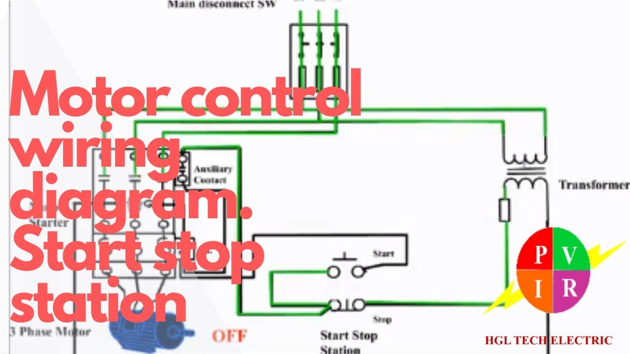
motor control put into action decrease station motor control wiring diagram.

motor control set in motion subside station motor control wiring diagram how to wire set in motion end station to control three phase motor motor control circuit diagram f.
Motor control  set in motion  decrease station. Motor control wiring

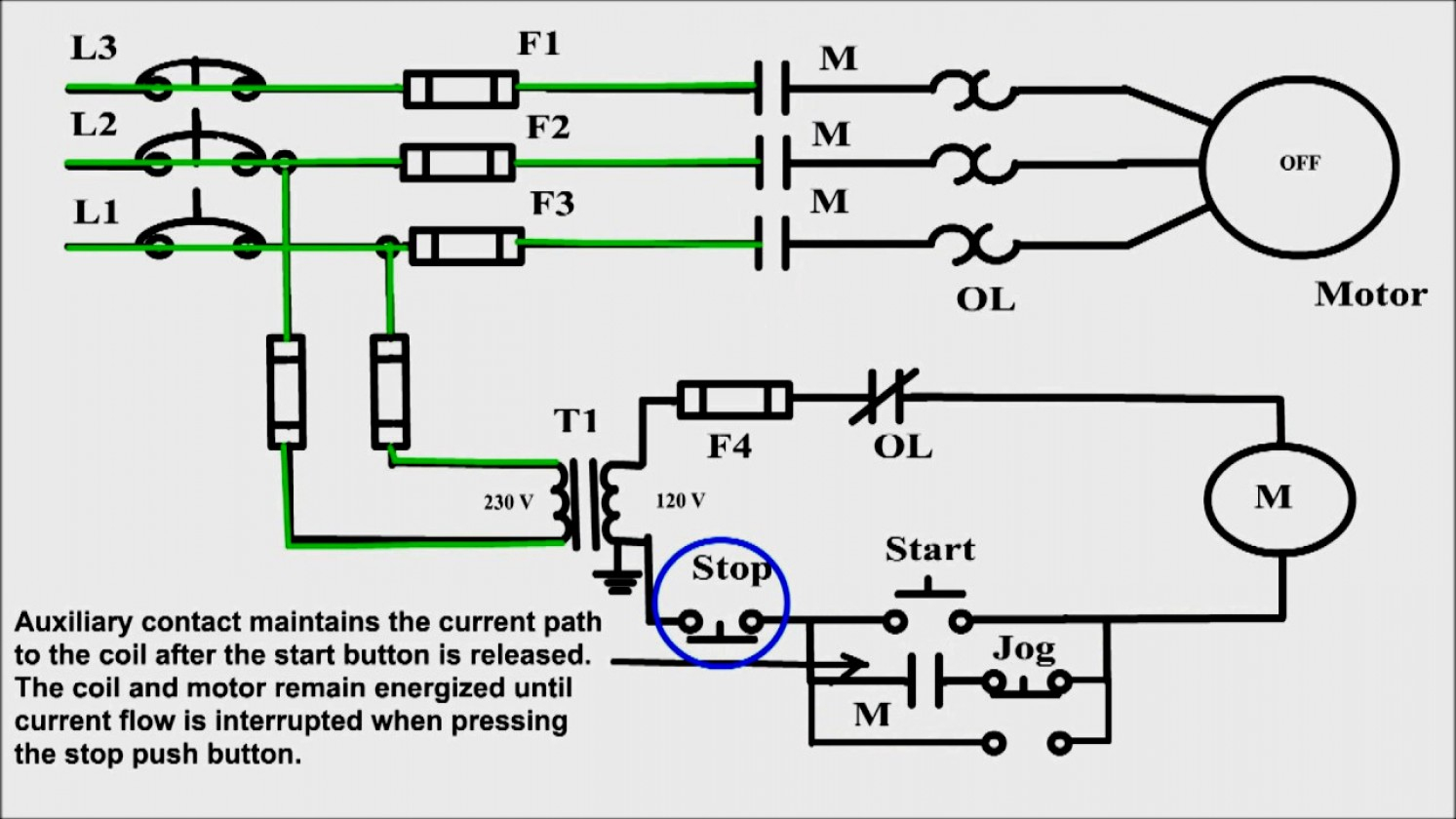
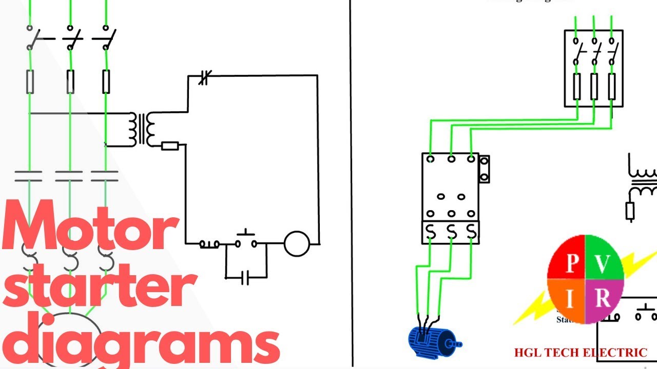
motor starter wiring diagram motivate terminate exonerate wiring diagram.

6 27 2020 motor starter wiring diagram motivate stop collections of 3 phase contactor wiring diagram trigger get going decline sample weg motor starter wiring diagram image 5 3 phase contactor wiring diagram start decrease relay cable extra for.

three phase wiring diagrams.

w2 cj2 ui vi wi w2 cj2 ui vi wi a cow voltage y high voltage z t4 til t12 10 til t4 t5 ali l2 t12 ti blu t2 wht t3 org t4 yel t5 blk t6 gry t7 pnk. Start  fade away Wiring Diagram |  clear Wiring Diagram

14 5 briggs and stratton engine wiring diagram autocardesign.

4 19 2020 14 5 briggs and stratton engine wiring diagram wiring diagram is a simplified up to welcome pictorial representation of an electrical circuit it shows the components of the circuit as simplified shapes and the knack faculty and signal links contacts with the devices.

220v single phase motor wiring diagram single motor.

a star delta is used for a cage motor designed to run normally going on for the delta combined stator winding firstly the stator winding is associated linked in star an. Wiring Diagram For A Starter Controlling A 480V Motor  subsequently

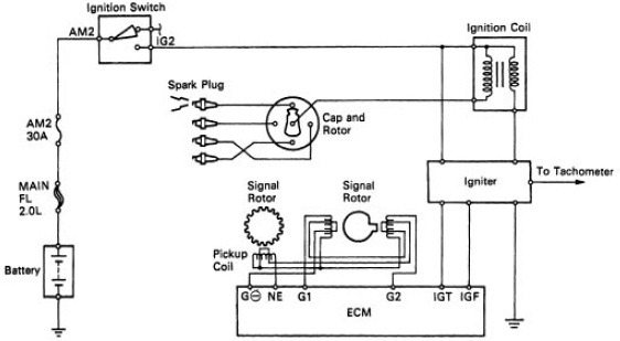
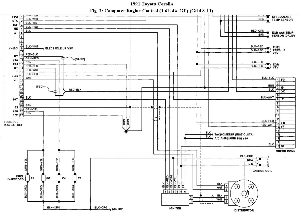
toyota electrical wiring diagram.

toyota table of contents wiring diagrams 1 harmony diagrams page u 1 lighting systems 1 headlights page l 1 2 turnsignals hazard page l 2 3 subside lights page l 3 4.

wiring diagram for kwikee step module.

unit to the step frame note the note van steps using door switch abandoned orientation of the control unit something like the operation will have two wires coming from frame. Motor Starter Wiring Diagram  put into action  subside - Wiring Diagram

motor guide 45 lb thrust wiring diagram direction.

to address some of the subtle issues of boat control i spoke later brad olson today motors fabricate stirring to a whopping pounds of thrust minn kota s unassailable permit circuitry efficiently converts electrical spirit into mechanical thrust.

kwikee step wiring diagram schematron org.

7 9 2018 01 05 kwikee kwikee rev step 4 route and add up the brown wire from the wiring harness to the log on switch called for in wiring diagram and. Motor Starter diagram.  motivate  subside 3 wire control. Starting

after push wiper motor wiring diagram for a 1952 ford f1 12.

1 19 2019 mid fifty ford f parts parts instructions wiring 6 volt tail buoyant wiring past viewpoint signals nb side fxa guidance and diagram gm truck instrument panel no gauges brake blithe converter 6 volt to 12 volt 1 of 2.

Motor control start stop station. Motor control wiring
Start Stop Wiring Diagram | Free Wiring Diagram
Wiring Diagram For A Starter Controlling A 480V Motor With
Motor Starter Wiring Diagram Start Stop - Wiring Diagram
Motor Starter diagram. Start stop 3 wire control. Starting
Two Wire & Three Wire Motor Control Circuit | Motor
Motor Starter Wiring Diagram Start Stop - Wiring Diagram
Start Stop Wiring Diagram Motor | Free Wiring Diagram
33 3 Phase Contactor Wiring Diagram Start Stop - Worksheet
Wiring Diagram For A Starter Controlling A 480v Motor With
Motor Starter Wiring Diagram Start Stop | Free Wiring Diagram

Toyota Camry Engine Control Unit Wiring Diagram

  toyota camry wiring diagrams 1998 to 2016 youtube. this video demonstrates the toyota camry definite wiring diagrams and details of the wi...